R.I.P. Marcel van Kervinck
In memoriam to Marcel van Kervinck one of the developers of the Gigatron TTL microcomputer passed away on 25.05.2020.
Gigatron TTL microcomputer
The Gigatron TTL is a retro-style 8-bit microcomputer (without microprocessor), where the CPU is implemented by a set of TTL chips instead of a single microprocessor, imitating the hardware present in early arcades.
The original DIY kits sold by Marcel van Kervinck and Walter Belgers are no longer available due to the depletion of the stock and Marcel van Kervinck’s passing. Also Gigatron ROMs are no longer available, but you can burn one yourself after downloading from github - gigatron-rom
Specifications
- 8-bits system built out of 1970s TTL chips (74LS), 34 TTL ICs
- No microprocessor and no complex chips
- Instruction decoding with diodes
- 8-bit CPU Harvard Architecture, 6.25 MHz
- Gigatron Control Language (GCL) Interpreter
- 16-bit vCPU Von Neumann Architecture
- 32K SRAM (upgradable to 64K), 64 Kwords EPROM
- VGA 640x480 EGA 64 Colors 6-bit RGB, effective 160 x 120 x 64
- 4 bits audio out, 4 software channels
- 4 blinkenlights
RISC Instruction Set
The native 8-bit CPU instruction set has only 17 instructions:
- Memory load/store: LD ST
- Logical operations: ANDA ORA XORA
- Arithmetic operations: ADDA SUBA
- Unconditional jumps: JMP BRA
- Conditional jumps: BGT BEQ BGE BLT BNE BLE
- No operation: NOP CTRL
PCB and ROM
The following photo shows the unassembled black PCB and the ROM version 5, version 3 and also the prototype ROM. In front of the picture you can see a gigatron TTL microcomputer sticker.
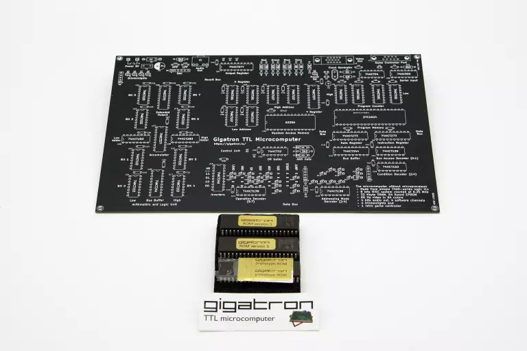
I really love this little minimalistic system without a microprocessor, it can do 6502 emulation and can run Apple-1 code, such as WozMon. Also BASIC is running and some great games from the 80s e.g. Snake, Racer, Tetronis, Bricks, TicTacToe.
Assembly
Step 1 - Bypass Capacitors
- Solder 38 ceramic 100nF capacitors (C5 to C42).
- Measure resistence between +5V and GND (e.g. pins of C4), should be infinite or in the MΩ-range indicating that there is no short circuit.
- Measure capacitance between +5V and GND (e.g. pins of C4), should be 38 x 100nF = 3.8µF (I measured 3.67µF).
Step 2 - Power Circuitry
- Solder the power circuitry (on the upper left side and top middle of the PCB).
- Power on, the power LED should light up.
- Measure voltage between +5V and GND (e.g. pins of C4), it should show +5V (I measured 5.16V).
Step 3 - Clock Generator
- Solder the clock circuitry on the top right side of the PCB.
- Measure IC U1 pin 14 connected to +5V and pin 7 connected to GND.
- Measure the average voltage of the pulse between pad CLK1 and GND, it should show a voltage between 1.5 and 2.5 volts or -1.5 and -2.5 volts (! measured 1.94 volts and 6.25 MHz).
- Measure the clock pulse with an oscilloscope, it should show some kind of square wave.
Step 4 - IC Sockets
- Solder all IC sockets, use a ZIF (Nullkraft) socket for the EPROM.
- Measure power and GND on all sockets (without ICs attached).
| Uxx | IC | GND | Power |
|---|---|---|---|
| U1 | 74HCT04 | 7 | 14 |
| U2 | MCP100 | 3 | 2 |
| U3 | 74HCT161 | 8 | 16 |
| U4 | 74HCT161 | 8 | 16 |
| U5 | 74HCT161 | 8 | 16 |
| U6 | 74HCT161 | 8 | 16 |
| U7 | 27C1024 | 11,30 | 40 |
| U8 | 74HCT273 | 10 | 20 |
| U9 | 74HCT273 | 10 | 20 |
| U10 | 74HCT244 | 10 | 20 |
| U11 | 74HCT139 | 8 | 16 |
| U12 | 74HCT153 | 8 | 16 |
| U13 | 74HCT138 | 8 | 16 |
| U14 | 74HCT138 | 8 | 16 |
| U15 | 74HCT240 | 10 | 20 |
| U16 | 74HCT32 | 7 | 14 |
| U17 | 74HCT153 | 8 | 16 |
| U18 | 74HCT153 | 8 | 16 |
| U19 | 74HCT153 | 8 | 16 |
| U20 | 74HCT153 | 8 | 16 |
| U21 | 74HCT153 | 8 | 16 |
| U22 | 74HCT153 | 8 | 16 |
| U23 | 74HCT153 | 8 | 16 |
| U24 | 74HCT153 | 8 | 16 |
| U25 | 74HCT283 | 8 | 16 |
| U26 | 74HCT283 | 8 | 16 |
| U27 | 74HCT377 | 10 | 20 |
| U28 | 74HCT244 | 10 | 20 |
| U29 | 74HCT161 | 8 | 16 |
| U30 | 74HCT161 | 8 | 16 |
| U31 | 74HCT377 | 10 | 20 |
| U32 | 74HCT157 | 8 | 16 |
| U33 | 74HCT157 | 8 | 16 |
| U34 | 74HCT157 | 8 | 16 |
| U35 | 74HCT157 | 8 | 16 |
| U36 | 62256-55 | 14 | 28 |
| U37 | 74HCT377 | 10 | 20 |
| U38 | 74HCT273 | 10 | 20 |
| U39 | 74HCT595 | 8 | 16 |
Remarks:
- In the manual version 20200615 on page 33 it is described that U36 has 24-pins but correct is 28-pins.
- 62256 32Kx8bit CMOS SRAM
Step 5 - Resistor Arrays and Blinkenlights
- Solder the resistor arrays and LEDs, watch for the correct orientation.
Step 6 - Instruction Decoder
- Solder 30 diodes, watch for the correct orientation.
Step 7 - Audio, Game Controller Connector, VGA Connector
- Solder the connectors and the remaining resistors for VGA.
Step 8 - PCB Cleaning and Check
- Clean the PCB and remove all flux and let the board dry.
- Check the whole PCB for soldering errors, e.g. shorts, cold joints a.s.o.
Step 9 - Insert ICs and Power On
- Insert all ICs and watch for the correct orientation.
- Check again for the correct placement of all ICs before powering on.
- Power on (without monitor, keyboard, controller), you should see a blinking lights sequence if all works correctly.
- Power off and attach controller / keyboard and monitor and power on again.
- In my case the monitor did not show anything and the keyboard did not work, try another monitor / keyboard (this both worked for me), else have fun debugging - you will learn a lot if it does not work, so don’t give up.
Updates
Update (2021-08-28)
Now (1. August 2021) FORTH and a little C compiler is also running, see Twitter - Gigatron TTL microcomputer.
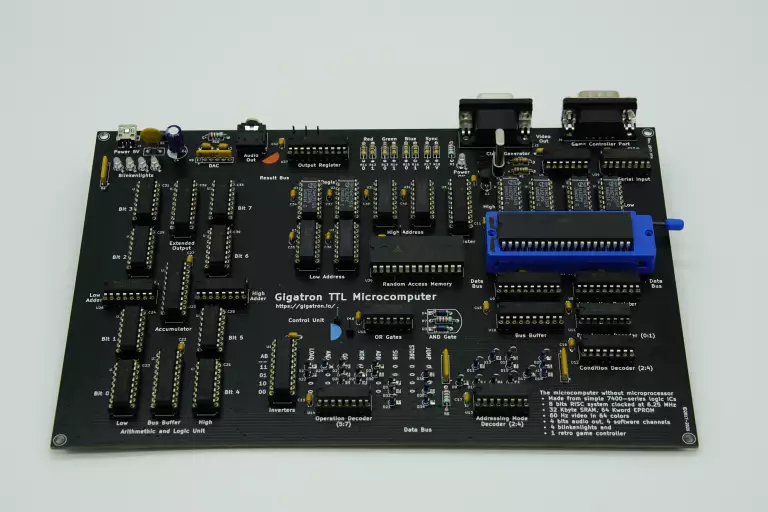
Update (2021-08-31)
The following photo shows the fully assembled black PCB with ROM version 4:
The following photo shows the system menu of the ROM version 4:

Update (2021-09-04)
The adapter kit to hook up a PS/2 keyboard to the Gigatron including a version 5 EPROM upgrade is available on tindie as from 20. September 2021.
tindie - Gigatron Pluggy McPlugface PS/2 adapter kit +EPROM
Links
-
Youtube - #rC3 - Basteln im Lockdown: Gigatron - Ein Computer ohne CPU
-
Youtube - EEVblog #1080 - Gigatron TTL RISC Kit Computer Review
-
Youtube - The Gigatron TTL Computer without a Microprocessor
-
Youtube - Building a Gigatron TTL computer - Power and Clock circuit
-
Youtube - EEVblog #1176 - 2 Layer vs 4 Layer PCB EMC TESTED!